Objective
Design the frame for the 25/26 formula car for Northwestern Formula Racing 2025/2026 based on the suspension geometry, 25/26 SES and 25/26 rulebook.
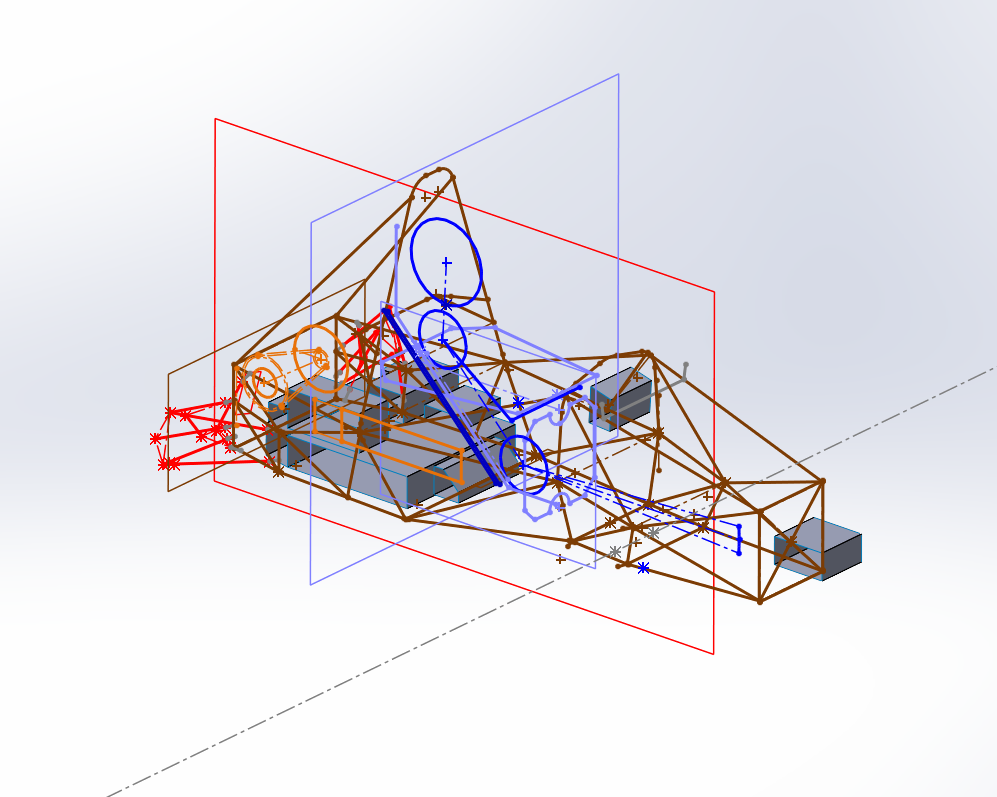
The suspension geometry was determined by the suspension subteam, and as frame designers we are expected to collaborate with ergo, suspension, chassis, accumulator and electrical subteams to ensure the frame integrates with all components of the car.
Major Design Considerations
The suspension geometry for NFR26 (the new car) features rockers in the front that required mount points on the frame.
New upright orientation required new mount points for suspension arms on the frame.
Steering wheel increased in size, which requires a taller front hoop.
Firewall backwards 3 in → driver backwards 3.5 in
Accumulator backwards 3.5 in
Front Bulkhead and Front Hoop backwards 2 in
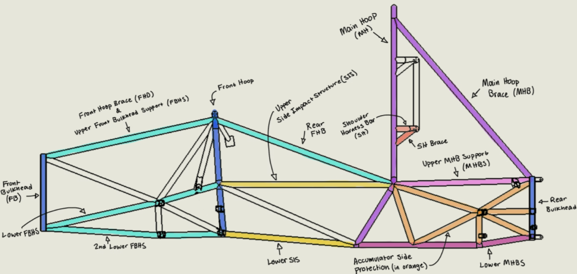
Frame Tube “Lingo”
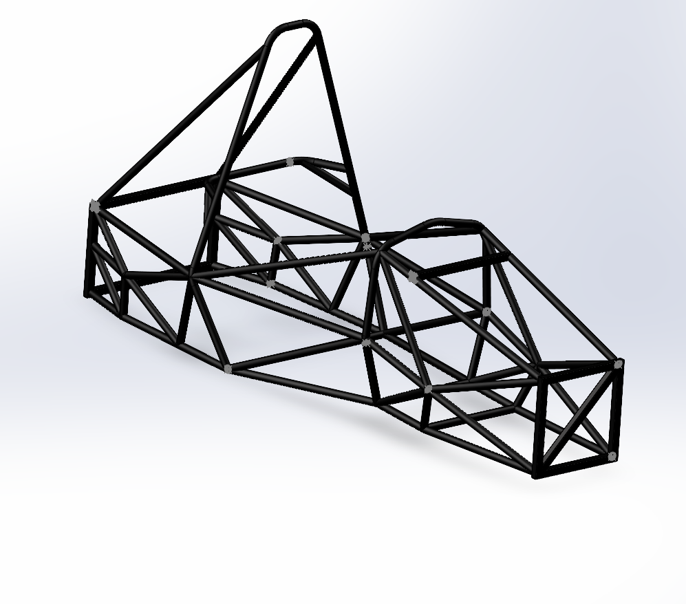
Frame Skeleton
My partner and I used the suspension geometry and block model of major car components to guide the skeleton creation. Abbreviations refer to frame labeling convention above.
Major skeleton changes:
New suspension geometry allowed for simplified front triangulation
FB and FH moved rearwards 2” to bring center of gravity further backwards
FH narrower to allow for longer sus tabs at nodes (1.25” → 1.5”)
Headrest mounting simplified to one frame tube + metal plate behind padding (plate not shown)
Distance between MH and FH shorter (31.8” → 29.5”)
Size of RB increased to protect accumulator
Frame skeleton with block model
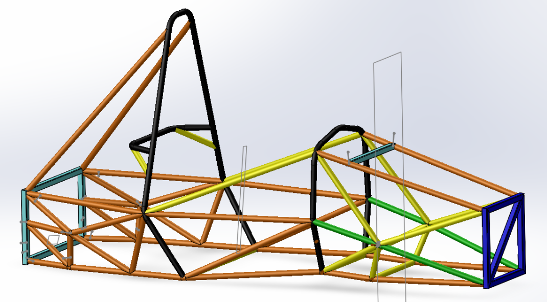
Tube Assembly
The tube assembly is created using the tube conventions provided by the FSAE 25/26 rulebook. We minimized the size of each frame tube, balancing safety and weight without violating the rules. All frame tubes and design elements are compliant with the Structural Equivalency Spreadsheet (SES).
In SolidWorks, we translated the frame skeleton into a parametric tube assembly using the Weldments feature, which allowed us to apply correct cross-sections, wall thicknesses, and joinery details. This approach enabled accurate weight tracking and ensured every member met the minimum dimensions and material requirements defined by the rulebook.
Tube Size Chart
1in x 0.095in
1in x 0.065in
1in x 0.058in
1in x 0.049in
1in x 1in x 0.049
1in x 1in x 0.065
Torsional Rigidity Case
My teammate and I performed torsional stiffness testing in ANSYS Workbench to compute the torsional rigidity case, importing the SolidWorks assembly and converting the tubes into beam elements. We connected the suspension points, constrained the rear bulkhead, and applied a pure couple by loading the left and right uprights with equal-and-opposite 1000 N remote forces. Because the analysis is linear-elastic and small-deflection, the absolute force value is not critical. Since any reasonable force gives the same T/θ ratio; we used 1000 N only to get a clear signal without leaving the linear range. We then extracted deformation data to calculate the twist angle, which gave a torsional stiffness of approximately 3406 Nm/deg, closely matching the stiffness of the previous year’s design.
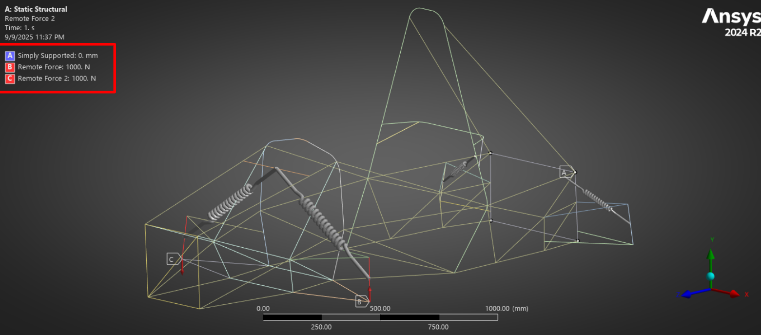
Torsional Stiffness Test Setup
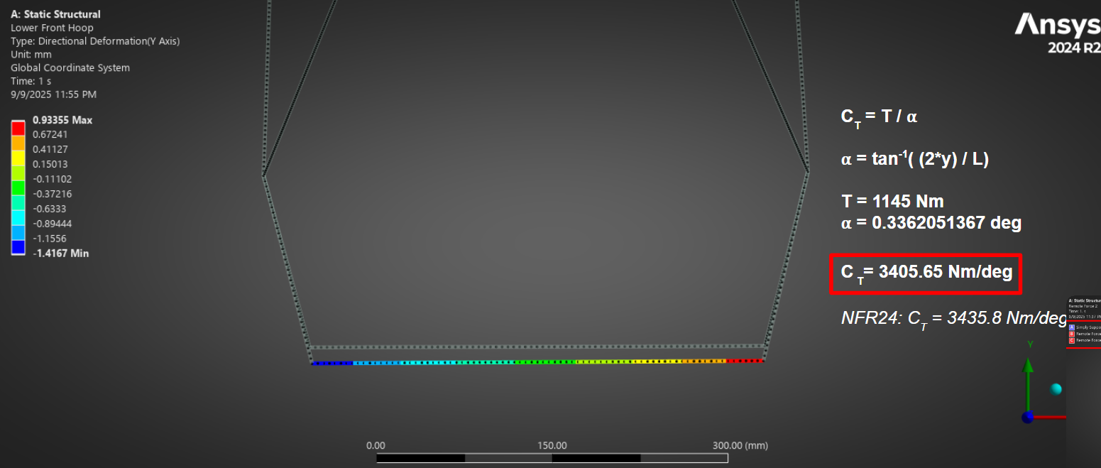
Results
Torsional Stiffness Testing Ansys
Up Next…
Currently, we are working on testing the bump cases for torsional stiffness testing. We also need to validate the deformation for the rear uprights. Once we have validated the frame through ANSYS, we will start researching how to set up our torsional stiffness rig.
I am also responsible for frame jigging for frame welding and have begun setting up the frame within the context of the base plate our team uses for jigging and welding.
More updates to come! Last Updated September 2025.
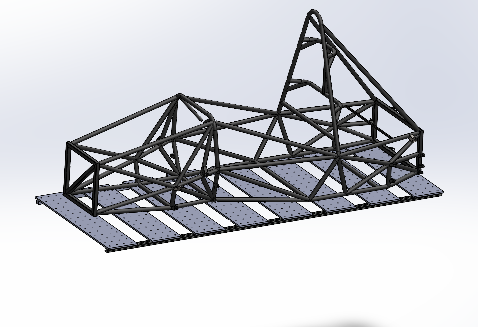
Frame and base plate