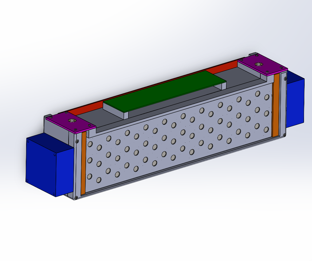
Tractive Battery Segment
Performance Analysis and Pack Sizing
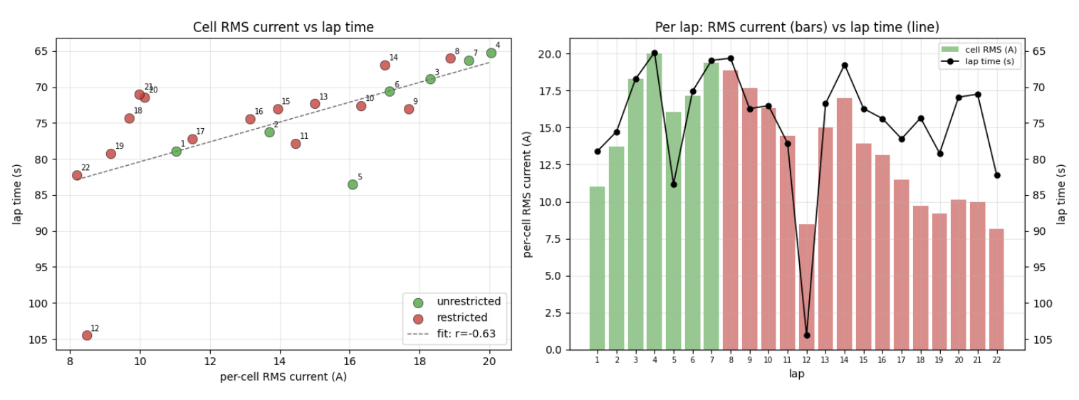
I began by analyzing NFR26 competition data to determine how much energy the new car would require and how battery current affected endurance performance. I compared total energy consumption, lap energy, lap times, RMS cell current, and measured temperatures against our existing simulations.
This analysis showed that increasing pack voltage and capacity could reduce current and resistive heat generation while maintaining the required power. It provided the quantitative foundation for selecting the NFR27 pack configuration rather than carrying forward the previous architecture unchanged.
6 x 20s3p = 120s3p
Segment Architecture
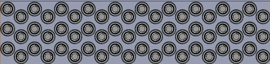
The current battery baseline is a 120s3p pack containing 360 Molicel P50B cells, producing 432 V nominal and 504 V maximum. I divided the pack into six identical 20s3p segments, creating equal, independently serviceable assemblies while remaining below the Formula SAE 600 V limit.
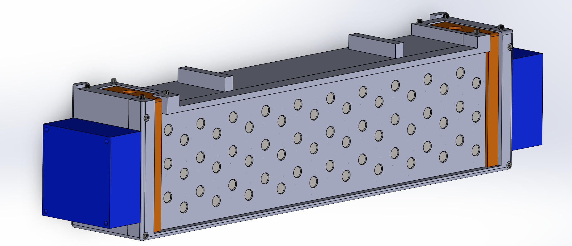
Each segment integrates 60 cells, structural cell holders, cooling airflow, current collection, maintenance plugs, voltage-sensing electronics, and protective covers. I arranged the cells in a staggered pattern to balance packaging density with the airflow required for cooling.
Air-Cooling Development
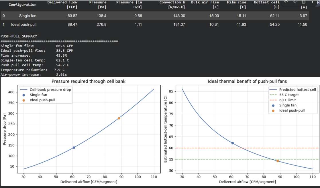
I developed a Python and Colab thermal model to compare air and liquid cooling and study the effects of cell current, spacing, pressure drop, fan selection, and air warming through the segment. The model evolved from basic energy-balance calculations into a coupled thermal and airflow sizing tool.
The current concept uses an 8 mm transverse cell gap and two high-pressure 80 mm Sanyo Denki fans per segment in a push-pull arrangement. I also incorporated the segment’s estimated 380 Pa pressure drop so that fan performance is evaluated at a realistic operating point rather than its unrestricted airflow rating.
Busbars
Boards
Mechanical and Electrical Integration
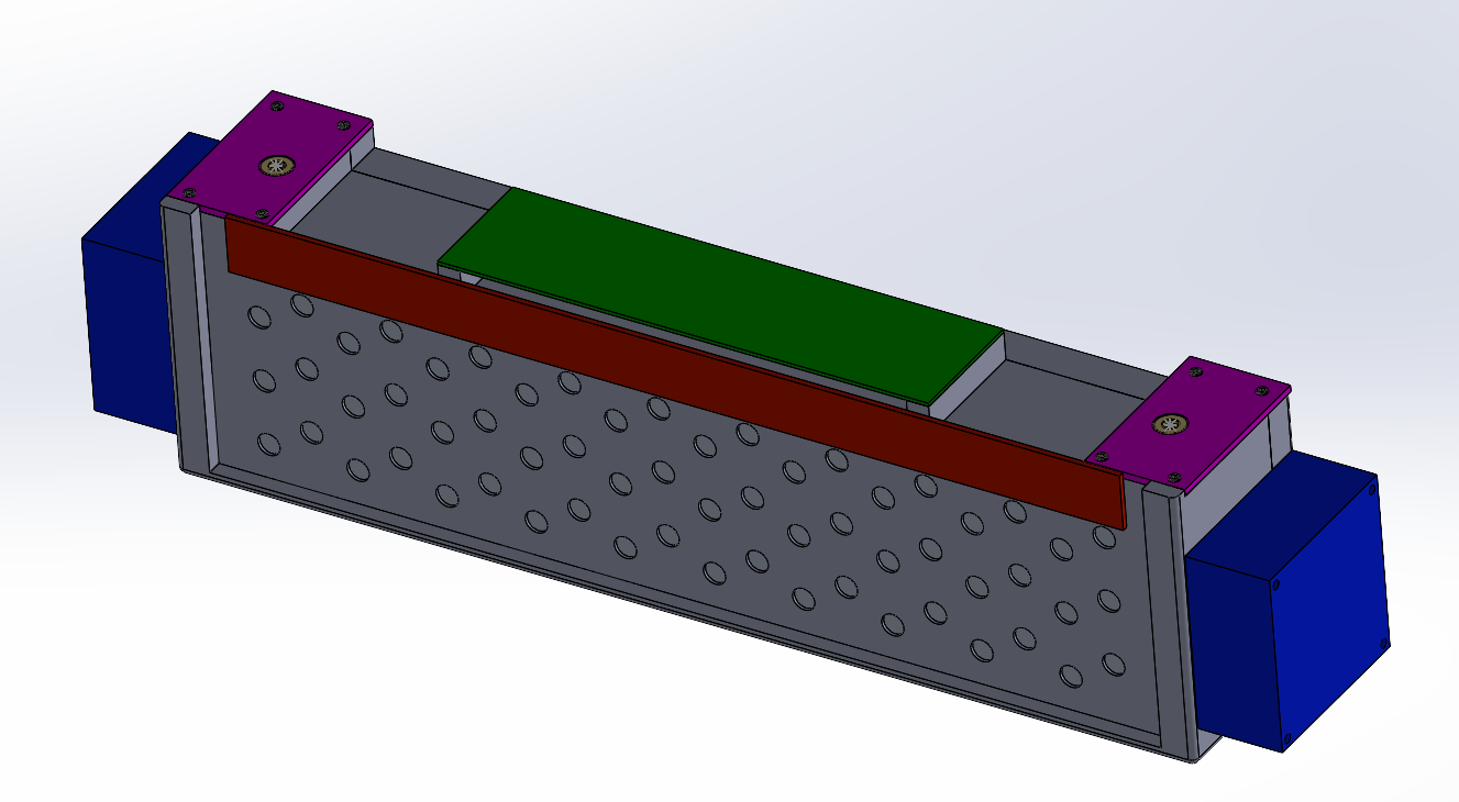
I designed the segment around two permanently joined 3D-printed cell holders using heat-set inserts and adhesive. The enclosed geometry minimizes uncontrolled openings that could reduce cooling performance while providing mounting features for the cells, busbars, maintenance plugs, and circuit boards.
Spot-welded nickel connects the cells, while formed terminal busbars route the segment positive and negative connections to positively locked maintenance plugs. A removable daughterboard and sense PCB provide voltage monitoring, with protective end covers shielding the exposed current-collection components.
Current Development
I am now moving the segment from its preliminary design into a build-ready and validated system. My current work includes validating the published fan curve, rerunning CFD with the final inlet geometry and pressure losses, evaluating the structure through FEA, and physically testing the nickel spot-welding process.
I am also finalizing the sense-PCB and daughterboard mounts, weld protection, printed materials, and enclosure details. These tests will determine whether the segment meets its thermal, structural, electrical, and serviceability targets before full-pack manufacturing begins.
Last Updated September 2026!